


Centralized Air Supply System
 1. Construction basis
1.1. "Industrial Metal Pipeline Engineering Construction and Acceptance Code" GB50235-2010
1.2. "Building Design Fire Protection Code" GB50016-2014
1.3. "On-site Equipment, Industrial Pipeline Welding Engineering Construction and Acceptance Code" GB50236-1998
1.4. "Scientific Laboratory Building Design Code" JGJ 91-93
1.5. "Hydrogen Use Safety Technical Regulations" GB 4962-2008
1.6. "Acetylene Station Design Code" GB 50031-1991
1.7. "Analytical Laboratory Water Specifications and Test Methods" GB6682-2008
 2. Technical requirements for gas circuits
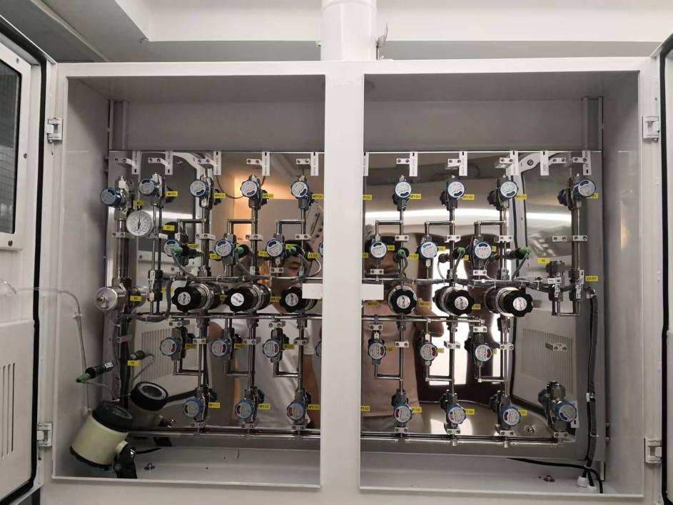
2.1 Overall system specifications
2.1.1 Gases are transported by stainless steel gas pipelines (BA grade); generally, there are brackets fixed to the wall every 1.5 meters.
2.1.2 In the gas cylinder room and each functional laboratory, the gas pipelines are fixed side by side on the wall or the laboratory table, and the equipment function board is installed on the wall next to the laboratory table 1.2-1.5 meters above the ground.
2.1.3 All gas and gas circuit labels are clearly visible and can withstand environmental changes.
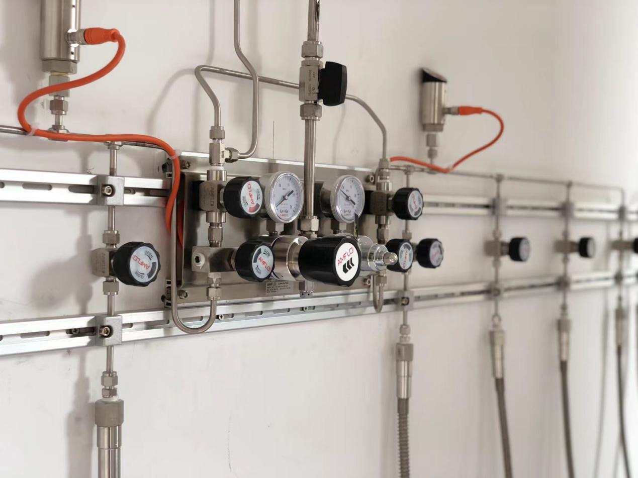
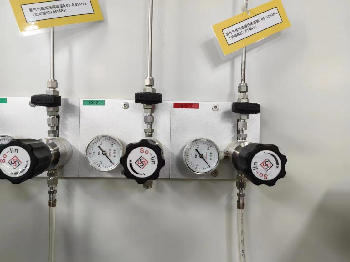
2.2 Gas cylinder connection and regulating valves in the gas source area.
2.2.1 All gas cylinders used are placed on the side against the wall without blocking the light in the laboratory.
2.2.2 All valves, pressure regulating devices, and pressure gauges are made of high-quality stainless steel materials and are standard accessories. The valve inlet and outlet are in the form of ferrules.
2.2.3 The high-pressure hose is made of stainless steel and has sufficient toughness.
2.2.4 The gas source and terminal and each room are clearly marked with the name of the gas.
2.2.5. Provide appropriate electrostatic grounding protection for the flammable and explosive gas busbars such as hydrogen and acetylene in the laboratory piping system.
 2.3. Gas pipelines
2.3.1. All gas pipelines are made of high-quality, fully annealed seamless stainless steel pipes (BA grade). The accessories and instruments used for hydrogen pipelines are special products for this medium and there is no substitute.
2.3.2. All pipelines are laid along the bottom of the ceiling. The branches of various gas pipelines introduced into the laboratory should be laid openly, and the pipelines for conveying dry gas should be installed horizontally. Gas pipelines should not be laid on the same rack with cables and conductive lines. Bending pipes are operated by special pipe benders, and cutting pipes are operated by special pipe cutters.
2.3.3. The spacing between gas pipeline brackets is not greater than 1.5 meters, and all bends must be supported independently on both sides. Air pipelines can be laid on the same rack with other gas pipelines, and the spacing between them is not less than 0.25m. The air pipeline is above other gas pipelines except hydrogen pipelines. All brackets used to support the installation of gas pipelines must be galvanized for corrosion protection.
2.3.4. When the hydrogen pipeline is laid in parallel with other combustible gas pipelines, the spacing between them shall not be less than 0.50m; when they are laid crosswise, the spacing between them shall not be less than 0.25m. When laid in layers, the hydrogen pipeline is located at the top.
2.3.5. All gas pipelines are connected by seamless welding. The relevant pressure accessories can only be used when connected to valves and pressure regulators.
2.3.6. The instrument workbench requires uniform discharge of various gas outlet points.
2.3.7. For instruments that require separate pressure regulation, separate valves need to be installed on the workbench to control the gas outlet points.
2.3.8. Stainless steel pipe fittings can only be unsealed during on-site installation. After unsealing, they must be purged with 5N high-purity gas before they can be connected to the system. After the entire system is installed, 5N high-purity nitrogen must be used for large-flow purge to ensure the cleanliness of the system.
2.3.9. Gas pipelines must be clearly marked by color and number, and the flow direction of the gas must be indicated.
2.3.10. Gas pipelines passing through laboratory walls or floors should be laid in pre-buried casings. There should be no welds in the pipe sections in the casings. Non-combustible materials should be used to seal the pre-casings of the pipelines.
 2.4. Gas pressure reducing valve
2.4.1. Busbar: used for non-strongly corrosive gases, applicable to gas purity (below 99.9999%), the accuracy of the pressure gauge, inlet pressure and maximum outlet pressure should meet the instrument requirements. Leakage rate < 10-3mbar.l/sec He, all materials are SUS316L.
2.4.2. Secondary pressure reducer: used for non-strongly corrosive gases, applicable to gas purity (below 99.9999%), the accuracy of the pressure gauge, inlet pressure and maximum outlet pressure should meet the instrument requirements. Leakage rate < 10-3mbar.l/sec He, all materials are SUS316L.
2.5. Acceptance In view of the above situation and actual working pressure, according to the relevant provisions of the "National Industrial Pipeline Installation and Acceptance Specification" (GB50235-97), "On-site Equipment, Industrial Pipeline Welding Engineering Construction and Acceptance Specification" (GB50236-98), a specific plan for the gas pipeline pressure test and purification of this project is formulated. The procedures are as follows:
2.5.1. Strength test: high-purity nitrogen PN2 is flushed into the pipe to make the pressure reach 1.2Mpa, and this pressure is maintained for 1 hour. If the internal pressure does not drop, it is qualified.
2.5.2. Air tightness: During acceptance, the inflation pressure is 1Mpa, and it is sealed for no less than 24 hours, and the pressure drop does not exceed 0.1Mpa.
2.5.3. Cleanliness test: high-purity nitrogen is filled into the pipeline, all valves are closed, and the end is opened to cover the pipe mouth with a clean white cloth for 1 minute. If there is no impurity and moisture on the white cloth, it is qualified.
Contact Us
Telephone: 0512-63169078 / 18015479868
Fax: 0512-63165028
E-mail: jshd@jshuadi.com
18015479868@163.com
Whatsapp: +86 18051830597
Wechat: +86 18051830597
Address:
Room 401, Building 13, No. 999 Xingdong Road, Jiangling Subdistrict, Wujiang District, Suzhou City, Jiangsu Province, China
Laboratory | Design Consulting | Equipment Development | Decoration | Fire Fighting