


Laboratory Airflow Organization Control System
 1. Construction basis:
1.1. "International Electrotechnical Commission Standard" (IEC)
1.2. "Electrical Installation Engineering Cable Line Construction and Acceptance Code" (GB50168-2018)
1.3. "Low Voltage Power Distribution Design Code" (GB50054-2011)
1.4. "Building Electrical Engineering Construction Quality Acceptance Code" (GB50303-2015)
1.5. "Automation Instrument Engineering Construction and Acceptance Code" (GB50093-2013)
1.6. "Electrical Installation Engineering Grounding Construction and Acceptance Code" (GB50169-2006)
1.7. "Laboratory Variable Air Volume Exhaust Cabinet" JG/T222-2007
1.8. "Laboratory Exhaust Cabinet Performance Test Method Variable Air Volume System Performance Test" ASHRAE 110-2016
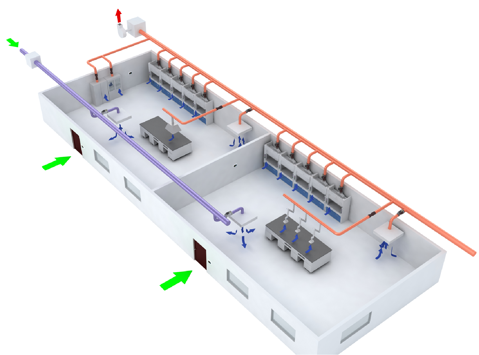
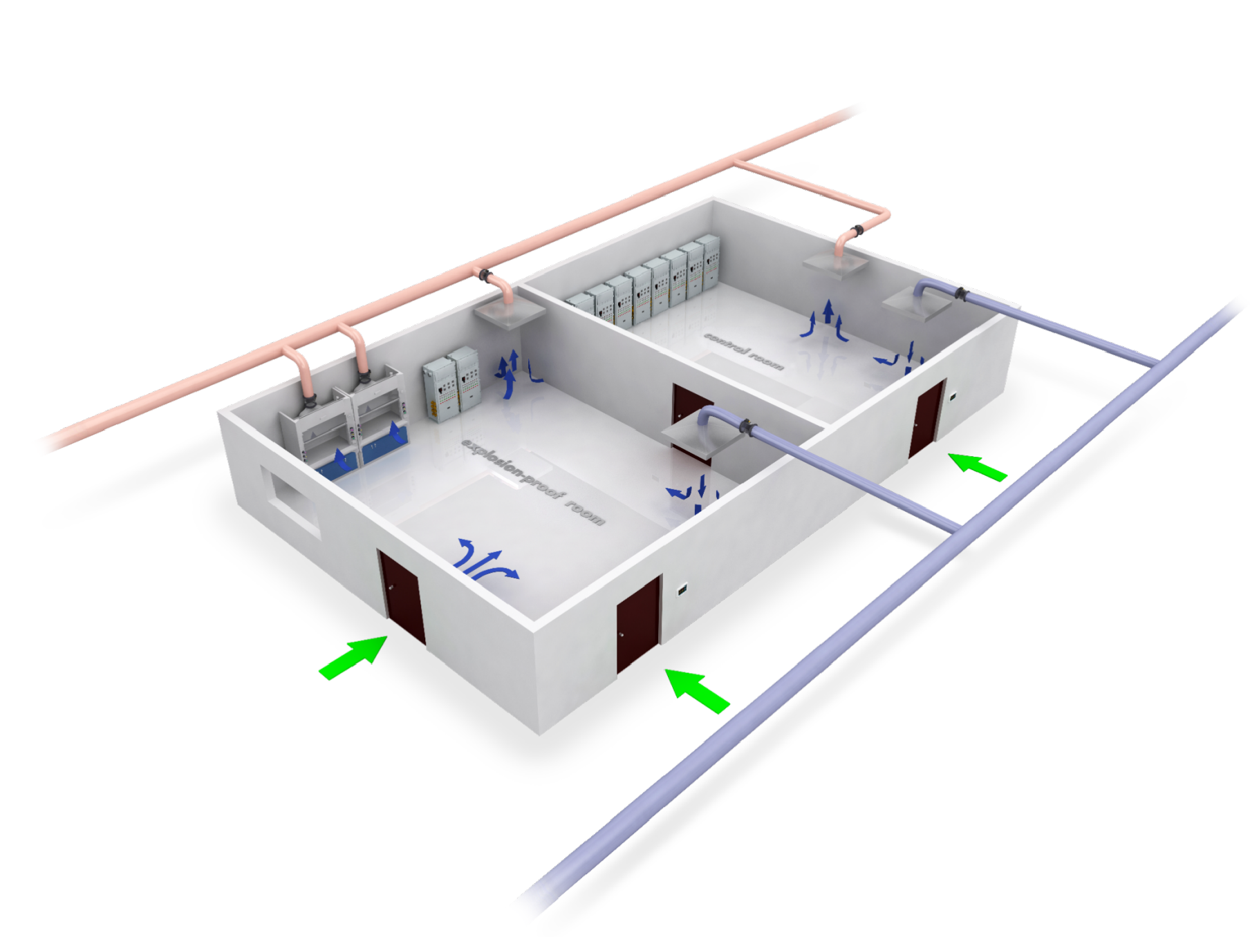
2. Technical solution for laboratory ventilation control system: Airflow control is the core of the entire laboratory. For the laboratory, in order to fully ensure that pollution does not leak from the laboratory contaminated area to the clean area or even the surrounding environment, to ensure the safety of the outdoor environment and the safety of the experimental operators, it is necessary to establish a stable and reliable airflow organization and ensure the stability of the laboratory airflow. Thus, a safe, reliable and effective protective barrier is established.
2.1. Technical solution for variable air volume control system of fume hood:
2.1.1. Venturi valve face wind speed control:
The following key indicators should be met by the bidder.
A displacement and face wind speed adjustment system is adopted. When the adjustment window moves, the controller adjusts the variable air volume exhaust Venturi valve to the calibrated air volume position according to the adjustment window displacement to maintain safe face wind speed. After stabilization, the measured face wind speed value is displayed in real time to determine whether it is within the safe range of face wind speed.
Each fume hood is equipped with a VAV control system. This control system ensures that when the fume hood adjustment door is in any position, the wind speed on the fume hood surface quickly stabilizes to the set value within 2 seconds, generally 0.5m/s. The system at least includes an anti-corrosion variable air volume exhaust Venturi valve, a display control panel, a face wind speed sensor, a displacement sensor, an automatic window system, and a power protection module.
 The system has the following functional characteristics:
(1) Automatically adjust to the safe surface wind speed setting requirements under different conditions;
(2) Sound and display alarm under unsafe conditions;
(3) Support night working mode, general working mode, low wind speed working mode, and emergency exhaust mode;
(4) Adopt TFT high-definition display panel, which is easy to clean and has high reliability;
(5) Support the measured surface wind speed LCD panel and various setting parameters;
(6) The system adopts a linear high-speed actuator, the actuator response time is within 1 second, and the overall system response time is within 2 seconds;
(7 ) It can support near-field communication, which is convenient for connecting with mobile phones, and can alarm to the mobile phone. The alarm notification and permissions can be set;
(8) The current temperature in the fume hood can be measured and displayed as needed;
(9) The system should have fire prevention and fire alarm functions, and the alarm point can be set and the alarm can be sent to the mobile phone;
(10) Support the automatic window system for adjusting windows;
(11) It has system flow measurement and reflects the current pipeline pressure to diagnose the working status of the system;
(12) The fume hood must ensure the minimum safe exhaust volume according to international standards;
(13) Supports display of current variable air volume valve status and opening size to remind users of fume hood usage status;
(14) Supports local keyboard direct operation to set or modify various parameters and function display screens;
(15) Supports emergency discharge function keys;
(16) 3-way custom relay input/output function for switch control of fans or lamps;
(17) Supports Modbus/BACnet standard protocol and can be directly connected to the automatic control system;
(18) Supports COM port connection to the local network.
 Technical requirements for product components:
1. European standard narrow-frame fume hood monitoring panel
(1) Ultra-narrow appearance design, width not exceeding 28mm, with high-definition LCD display, which can display the current fume hood face wind speed value or exhaust volume in real time. The monitoring panel adopts a display screen plus membrane button design;
(2) Narrow and long strip structure, all function buttons are arranged vertically;
(3) Support displacement and air volume control mode, can be accurately adjusted according to the measured exhaust volume value to maintain constant face wind speed;
(4) Fume hood air volume accumulation can be performed;
(5) All parameters can be set on-site, the LCD display should have corresponding adjustment instructions, and the interface should be password protected to avoid misoperation;
(6) Support near-field communication or WIFI communication, easy to connect to mobile phone communication, can alarm to the mobile phone, and alarm notification and permissions can be set;
(7) Equipped with an emergency exhaust button. In an emergency, this button can be used to achieve maximum exhaust operation;
(8) The system has a mobile phone debugging software, which can be used to set, modify, view parameters, and perform emergency operations;
(9) It has the functions of normal operation, standby operation and off mode. When the fume hood is not used for a long time, it can be switched to off mode and the exhaust valve is fully closed.
(10) The safe/dangerous operating status can be displayed on the LCD, and the upper and lower limits of the surface wind speed and the adjustment window displacement alarm can be set; it supports temperature measurement, display and alarm in the cabinet, and the sound and light alarm can be switched to silent mode.
(11) It can alarm for a variety of dangerous conditions, including abnormal wind speed, sensor failure, adjustment window too high, valve actuator failure, and can also expand other alarm functions, such as high temperature.
( 12) It supports the automatic displacement system of the adjustment window, which can be controlled through the mobile phone, and the authority can be set.
(13) The fume hood must ensure the safe minimum exhaust volume according to international standards.
(14) It supports the display of the current variable air volume valve status and opening size to remind the user of the fume hood usage status.
(15) The 3-way custom relay input/output function is used for switch control of fans or lamps.
(16) It supports Modbus/BACnet standard protocol and can be directly connected to the automatic control system.
(17) It supports COM port connection to the local network.
2. Surface velocity sensor
(1) Installed on one side of the fume hood, actually measures the surface velocity of the fume hood, measuring range: 0-2m/s; measurement accuracy ±5.0%;
(2) The sensor measurement should adopt the thermistor NTC direct measurement method, and the internal comparison thermistor module can be automatically calibrated regularly;
(3) The sensor should have a reference calibration and will not have accuracy drift with use;
(4) The sensor installation should be suitable for various types of fume hoods;
(5) The input power is: 24VDC, the output signal is: 4-20mA/0-10V;
3. Displacement sensor
(1) The control system must use an adjustable window displacement sensor to ensure the reliability of the control system operation;
(2) The high-precision potentiometer is equipped with a 0.7mm steel wire, which is directly connected to the adjustable door or its counterweight;
(3) When the adjustable door switch changes, the resistance of the potentiometer changes, and a 0-10VDC adjustable door opening signal is generated on the fume hood controller;
(4) The stroke range is 0-1000mm, suitable for general fume hood adjustable windows;
(5) Hub material: insulating particle coated anodized aluminum;
(6) Measurement accuracy: <0.2mm;
(7) Repeatability: <0.1mm;
(8) Installation method: fixed bracket or threaded installation.
4. Fume hood variable air volume Venturi valve (aluminum alloy spraying)
The fume hood variable air volume exhaust control valve adopts high-precision (within ±5% of the reading) and high-speed response air volume control equipment. It has a self-adjusting mechanical structure that is not affected by the static pressure change in the pipeline (150Pa-750Pa) and accurately maintains the set air volume. According to the change in the required air volume, it can complete accurate air volume control in less than 1 second to prevent the spread of harmful gases.
The variable air volume exhaust control valve of the fume hood must have the following characteristics:
(1) Air volume control accuracy: ≤ ±5% of the controlled air volume;
(2) Air volume calibration: Air volume calibration before leaving the factory, the calibration points shall not be less than 48;
(3) Mechanical pressure independence (flow rate remains constant within the range of 150Pa-750Pa);
(4) High-speed response, response time is less than 1 second (to deal with pipeline static pressure fluctuations <1 second, to deal with control changes <1 second), with 0-10VDC flow feedback;
(5) Adopting original imported brand high-speed linear silent actuator, the stroke noise is less than 40dB;
(6) Aluminum valve body and cone with anti-corrosion coating; SS316L stainless steel is used for valve internal connectors;
(7) High adjustment ratio 16:1;
(8) Actuator speed <1 second (full stroke);
(9) No straight pipe section required;
(10) Noise: Low noise design meets or exceeds ASHRAE noise standards;
(11) Safety measures: When power is off or fails, the air valve should be in the maximum exhaust state (normally open state).
5. Fume hood infrared area sensor
(1) Adopts active infrared detection technology sensor;
(2) Radiation range: 2300mmx80mm (adjustable);
(3) Sensing beam: 12 beams;
(4) Sensing time <50ms;
(5) No accuracy drift during use;
(6) LED status indication;
(7) Detection time interval can be set (usually 3min/10s);
(8) Automatic sensing switch, digital output.
6. Automatic window system
(1) Opening the window: The user only needs to gently lift the adjustment window, short press the "+" button on the monitoring panel, or lightly step on the foot switch to automatically raise the adjustment window to the set safe operating height. The user can also press and hold the "+" button on the monitor to raise the adjustment window to any position.
(2) Lowering the window: The user only needs to gently pull the adjustment window down, short press the "-" button on the monitoring panel, or when the infrared area sensor detects that there is no one and it lasts for more than a preset time, the adjustment window will automatically lower to the lowest position. The user can also press and hold the "-" button on the monitor to lower the adjustment window to any position.
(3) Preventing foreign objects: When foreign objects, laboratory instruments, human hands, etc. appear under the window, the infrared safety beam will immediately stop the window from lowering to prevent losses.
(4) Supports near-field communication or WIFI communication, which is convenient for connecting to mobile phones. It can alarm the mobile phone, and the alarm notification and permissions can be set.
(5) Monitor and automatic displacement power supply: 15~30VDC;
(6) The automatic window integrated controller adopts an integrated aluminum profile shell, and the terminal has a clear nameplate and indicator light;
(7) Host computer communication: RS485 Modbus RTU.
7. Overall requirements
(1) To ensure system stability and seamless connection, the fume hood variable air volume control system, including sensors, controllers, variable air volume exhaust venturi valves, etc., should maintain control integrity and maintenance reliability. Products in the system cannot be replaced or combined.
(2) To ensure product quality and laboratory stability, variable air volume control must use excellent brand products
(3) The fume hood face wind speed sensor and displacement sensor should be applicable to most construction conditions and building standards, as well as the fume hood structures of different standards, specifications, and manufacturers. At the same time, it should be able to reasonably represent the average face wind speed of the fume hood;
2.1.2, Butterfly valve variable air volume control system
1. Overall requirements of the system
(1) In the opening area of the operation surface of the fume hood, the average surface wind speed reaches: 0.5M/S±15%, which meets the requirements of the national standard "JG/T222-2007";
(2) The face air speed control system continuously monitors the actual exhaust air volume of the fume hood, and calculates the exhaust air volume corresponding to the window opening area based on the window height. When the exhaust duct pressure changes or the window height changes, the system responds quickly and responds And the stabilization time is ≤1S;
(3) The variable air volume exhaust valve at the top of each fume hood should be a quick-response butterfly valve. Anti-corrosion, air tightness and structural strength requirements should also be taken into consideration. The valve used should be a molded one-piece PPs butterfly valve with a The silicone air-tight ring ensures high air tightness, and the flow detection section with Venturi effect accurately measures the exhaust volume; to ensure the long-term stability of the system and resistance to chemical corrosion, there must be no corrosive parts such as electronic components, wires, and metals in the valve body.
2. System Function Requirements
(1) The system adopts a dual control method of displacement and pipe actual measured air volume and demand air volume comparison, directly measuring and displaying the current average surface wind speed and air valve opening status, current cabinet temperature, and actual height of the window (digital) on the color LCD display Display the actual height, such as 40CM, the user can directly and clearly understand the current status of the VAV system, which cannot be replaced by percentage or other display methods), human body sensing status, system status, delayed shutdown status, automatic window control status, etc.;
(2) Automatically adjust the air volume to constant the safety surface wind speed under different conditions;
(3) Under unsafe conditions, sound and digital display alarms are provided, and there is an alarm silence button to eliminate the alarm sound;
(4) Face wind speed automatically switches between manned and unmanned operation;
(5) When the fume hood door is fully closed, the minimum exhaust air volume is maintained, and the 1500MM fume hood is 300CMH;
(6) Fume hood window over-limit height/surface wind speed over-limit alarm;
(7) The temperature in the fume hood exceeds the limit alarm;
(8) Delayed automatic shutdown, which can automatically shut down the system after exhausting the air according to the set time after the operator leaves, which is safe, convenient and energy-saving;
(9) All valves should be closed when the fume hood is not in use;
(10) Emergency discharge function when an accident occurs;
(11) Manual/automatic control of the fume hood lighting. During automatic control, the lighting status automatically switches between manned and unmanned operation;
(12) The control module supports Modbus universal network protocol and can be connected with the building intelligent centralized monitoring system;
(13) User parameter settings need to support: face wind speed control (manual/automatic) mode setting, lighting (manual/automatic) mode setting, working surface wind speed setting, standby surface wind speed setting, window safety height setting, temperature User parameter settings such as upper and lower limit settings, delayed shutdown time setting, etc.;
3. Product configuration requirements
(1) Control panel and controller
A. It has a full-color LCD panel, the overall screen is not less than 4.3 inches, a resistive full monitoring panel (full-screen switchable interface), and has display and direct operation functions. The display interface can be switched between the main interface, user parameter interface, and system parameter interface. All parameters (including real-time average surface wind speed value, valve opening, temperature, etc.) can be set locally. The LCD display should have corresponding instructions for adjustment. And password protection should be set when entering the parameter interface to avoid misoperation. All buttons are independent buttons for easy cleaning and high reliability. Independent buttons such as system start and stop, lighting control, emergency exhaust, exhaust delay automatic shutdown, alarm silencer, etc. can be set for quick and direct operation functions;
B. Supports dual-channel control mode of displacement and comparison of measured air volume and demand air volume in the duct, and quickly adjusts through the displacement sensor. After the adjustment window is stabilized, precise adjustment is performed based on the comparison between the measured air volume and the demand air volume in the duct to maintain a constant surface wind speed;
C. Equipped with an emergency exhaust button. In an emergency, maximum exhaust operation can be achieved through this button;
D. It has working and standby mode operation, and can automatically switch the fume hood to standby operation through human body induction to reduce energy consumption;
E. It has a system shutdown mode. When the fume hood is not used for a long time, the system shutdown mode can be switched and the exhaust valve is fully closed;
F. Can provide alarm prompts for a variety of dangerous states, such as: including abnormal wind speed (super high/low) alarms, ultra-high window alarms, excessive temperature alarms, etc.;
G. The safe/dangerous operating status is displayed on the LCD screen, and the upper and lower limits of the working average surface wind speed, the standby average surface wind speed, and the adjustment window displacement alarm can be set. With sound and light alarm function, silent mode can be set;
H. Equipped with multiple customized expansion functions (such as germicidal lamp control, multi-door fume hood control);
I. The controller supports Modbus universal network protocol, and all data is uploaded to centralized monitoring and unified monitoring and management;
(2) Variable air volume butterfly valve
A. The variable air volume butterfly valve must be a product of excellent brand, and should be a fast variable air volume control valve designed for the special requirements of chemical laboratories. The variable air volume valve should have fast response capability, high air tightness, and be made of PPs material with many characteristics such as high corrosion resistance and fire resistance. The diameter is 250mm, and the molded one-piece molding ensures high strength and durability. It has a Venturi effect measurement section and accurately measures the air volume;
B. Actuator drive mode: The full stroke of the high-speed electric actuator is ≤2.5 seconds, and an internationally renowned brand original imported actuator must be used;
C. The actuator control module has its own feedback microprocessor to achieve high stability;
D. The connection between the shaft and the valve body uses a low-damping material self-lubricating connection to minimize the actuator resistance. In order to improve the anti-corrosion ability, no metal parts are allowed in the part that contacts the exhaust gas;
E. The shaft and butterfly blade are molded into one piece to ensure high corrosion resistance; the valve leaf is equipped with a silicone sealing ring to ensure airtightness;
F. Connection method: It has both flange connection and direct plug-in connection to facilitate on-site pipeline docking construction.
(3) Flow sensor
A. To ensure the accuracy of the average face velocity of the fume hood, the measurement value of the single-point face velocity sensor cannot be used to represent the measurement method of the average face velocity. The average face velocity must be calculated by comparing the actual measured air volume in the duct with the required air volume.
B. The flow sensor must be of imported brands or domestic high-end brands.
C. The sensor should have a benchmark calibration and will not drift due to temperature changes or long-term use, avoiding regular calibration and reducing the complexity of maintenance.
D. The flow detection device is installed in the pipeline, and the sensor is installed outside the air duct and connected with an air pipe. It is higher than the position of the detection device to prevent liquid backflow. The actual measurement of the exhaust volume of the fume hood has a range of 100-2000M3/h; accuracy ±1%FS;
E. The sensor installation should be suitable for various types of fume hoods.
(4) Displacement sensor
A. The control system must use a window displacement sensor to ensure the reliability of the control system operation.
B. The high-precision potentiometer is equipped with a plastic-coated stainless steel cable (the diameter of the steel cable is not less than 0.6mm), and the cable is directly connected to the regulating door or its counterweight.
C. The measurement accuracy is better than 1mm, the repeatability is better than 1mm, and it is automatically calibrated. The measuring range is not less than 0-1100mm, and a well-known brand with high reliability and good durability is selected;
D. As the position of the regulating door moves, the resistance of the potentiometer changes, and a 0-10VDC regulating door opening signal is generated on the fume hood controller;
E. The outer shell is made of corrosion-resistant PP material;
F. Installation method: fixed bracket or threaded installation;
(5) Area presence sensor
A. Configure area status sensor (occupancy sensor);
B. Installed above the fume hood, using curtain-type infrared sensing;
C. The detection time interval can be set (usually 3min/10s);
D. LED status indication;
E. The detection signal is transmitted to the fume hood monitoring panel for automatic switching of automatic face wind speed mode, automatic lighting mode, etc., and the delay switching time can be set;
(6) Temperature sensor
A. Measurement temperature range: -50℃—125℃, measurement accuracy 1%, no accuracy drift, automatic calibration, alarm and start emergency exhaust when the temperature exceeds the set value;
B. Material: The entire sensor is made of stainless steel including the probe and connection parts;
C. The connecting cable has a stainless steel shield;
D. Installed above the fume hood body.
2.1.3. Technical solution for room residual air volume control
(I) General description
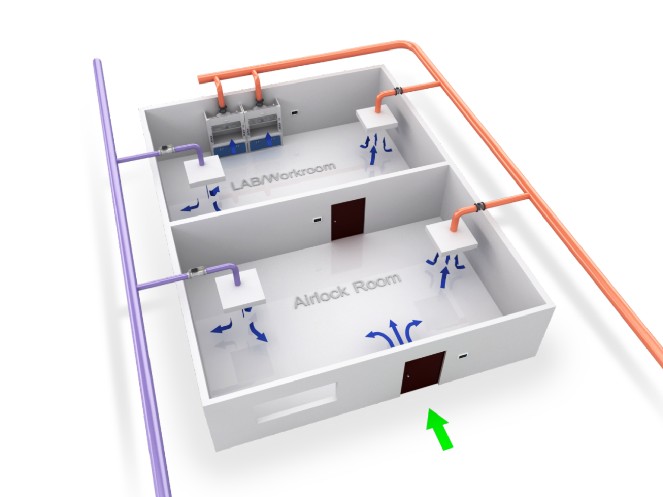
The laboratory has many variable air volume equipment such as fume hoods and fixed air volume exhaust equipment. This area uses a lot of toxic and harmful solvents, needs to exhaust a lot of waste gas, and has frequent personnel and logistics. Therefore, the room should adopt an air volume difference control solution to collect the exhaust volume changes caused by the use status changes of the exhaust equipment in the room. By setting the difference between the supply and exhaust air volume, the controller controls the regional air supply valve to adjust the fresh air volume in the area, so as to control the room air supply to achieve micro-negative pressure and correct and stable air flow direction.
(II) System composition
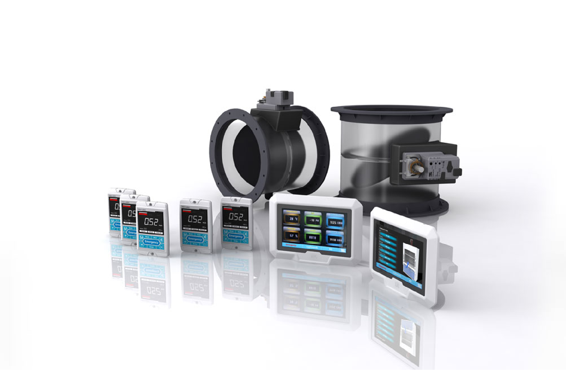
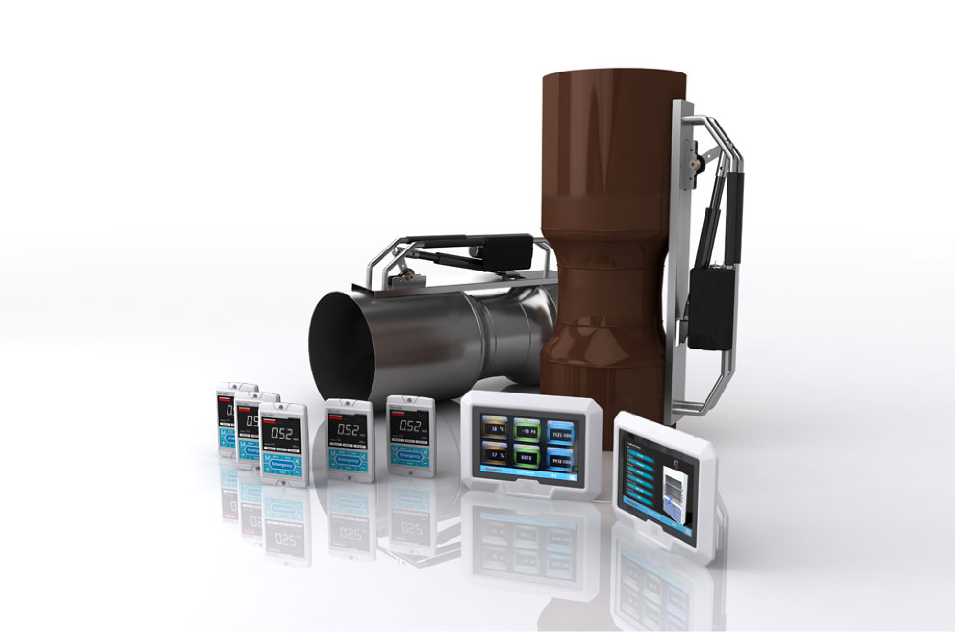
The system consists of: variable air volume supply electric valve, supply air flow detection device and sensor, switch exhaust electric valve, controller and control box, monitoring panel, exhaust equipment and fume hood control system and collection system and other components.
(III) Control requirements
(1) The variable air volume supply/exhaust electric valve actuator adopts a three-wire analog control method and can stay freely at any position. The full stroke of the high-speed electric actuator is ≤2.5 seconds. The original imported actuator of an internationally renowned brand must be used;
(2) The flow sensor is installed on the air duct to actually measure the duct air volume. The sensor should have a benchmark calibration and will not drift due to temperature changes or long-term use, avoiding regular calibration and reducing the complexity of maintenance;
(3) The system collects the exhaust volume changes caused by the use status changes of the exhaust equipment in the room. By setting the difference between the supply and exhaust air volumes, the controller controls the regional air supply valve to adjust the fresh air volume in the area, thereby controlling the room supply air to achieve micro-negative pressure and correct and stable airflow direction;
(4) The room monitors VOC data in real time. When the data exceeds the range, it automatically alarms to remind the user and triggers emergency exhaust of the room;
(5) The room monitors CO2 data in real time. When the data exceeds the range, it automatically alarms to remind the user;
(6) The room monitors temperature data in real time. When the data exceeds the range, it automatically alarms to remind the user;
(7) The room monitors humidity data in real time, and automatically alarms to remind the user when the data exceeds the range;
(8) Each control system is equipped with a 10-inch monitoring panel (with RJ45 interface supporting Ethernet communication protocol); LCD interface demonstration: It has at least multiple custom indicators of input and output display and control functions, including the total exhaust volume of the room, the total supply air volume, the residual air volume value, the supply fan status, the exhaust fan status, the room operation status, the current room fume hood operation status, the fume hood face wind speed, the fume hood window height display, the fume hood lighting status, whether there is someone in the fume hood, the fume hood temperature value, the system time, one-button start and stop control, the alarm information list, the timed start and stop control and setting, the emergency exhaust control, etc.;
(9) The controller is equipped with Modbus general network protocol and industrial Ethernet general network protocol, and can be connected to the intelligent centralized monitoring and management system.
4.The system should at least have the following functions:
(1) Summarize the total exhaust volume of the room in real time;
(2) Measure and control the total supply air volume of the room in real time;
(3) The system can automatically start and stop at the set time;
(4) The system has a one-button emergency exhaust function;
(5) Real-time alarm in unsafe conditions;
(6) Real-time monitoring of room air quality (VOC, CO2, temperature, humidity).
2.1.4. Room multi-stage control system
(I) General description
Rooms with multiple sets of fixed air volume exhaust equipment use a room multi-stage fast supply and exhaust linkage control system. The room multi-stage fast supply and exhaust linkage control system samples the changes in the use status of multiple sets of fixed air volume exhaust equipment in the room. According to different working conditions, the controller control system controls the air supply regulating valve to adjust the amount of fresh air supplied to the room, thereby controlling the room supply air to achieve the purpose of micro-negative pressure in the room. The system starts and stops in linkage with the fixed air volume exhaust equipment and supply and exhaust fan system in the relevant area.
(II) System composition
The system consists of: switch exhaust electric valve, variable air volume supply electric valve, controller and control box and other components.
(III) Control technology solution
(1) The electric valve for constant air volume exhaust can be freely stopped at any position, which is convenient for simple air volume adjustment of the supply/exhaust terminal;
(2) The system collects the exhaust volume changes caused by the use status changes of the exhaust equipment in the room, and controls the regional air supply valve to adjust the fresh air volume in the area by setting the difference between the supply and exhaust air volume, so as to control the room air supply to achieve micro-negative pressure and correct and stable air flow direction;
(3) The control system automatically controls the supply air regulating valve to adjust the amount of fresh air delivered to the room according to the use status changes of the constant air volume exhaust equipment. The angle parameters of the relevant supply and exhaust air electric valves can be quickly set on the monitoring panel according to user needs;
(4) To facilitate users to adjust the supply and exhaust air volume of the room: the angle parameters of the electric valve of the constant air volume equipment can be independently set on the monitoring panel. When the fan starts and stops, the unit operation feedback is abnormal, and after a certain period of time, the system automatically determines that it is a fault;
(5) The controller is configured with Modbus general network protocol and industrial Ethernet general network protocol, and can be connected to the intelligent centralized monitoring and management system.
(IV) The system should at least have the following functions:
(1) Independent start and stop control of exhaust equipment;
(2) Control of the total air supply volume in the room;
(3) The system can automatically start and stop at the set time;
(4) Sound and display alarms under unsafe conditions;
(5) User parameters and system parameters such as the corresponding parameters and angles of the electric valve;
(6) Real-time display of the unit status.
2.1.5. Room constant air volume equipment control system
(I) General description
(1) Universal hoods, atomic absorption hoods, etc. are defined as constant air volume exhaust equipment;
(2) Rooms that only have constant air volume supply equipment are defined as: fixed supply control;
(3) Rooms where the exhaust only has constant air volume equipment such as universal hoods, atomic absorption hoods, etc., and the room supply is constant air volume supply; defined as: fixed supply and fixed exhaust control;
(4) Rooms where the only constant air volume exhaust equipment such as universal hoods, atomic absorption hoods, etc. are defined as: fixed exhaust control.
(II) System composition
The system consists of control switches, air supply electric valves, air exhaust electric valves, controllers, control boxes, monitoring panels and other components.
(III) Control technology solution
(1) The air supply/exhaust electric valves can freely stay at any set position, which is convenient for simple air volume adjustment of the air supply/exhaust terminal, and has a memory function (that is, it can remember the angle adjusted this time and still adjust it to the designed angle when it is opened next time);
(2) The control switch signal is directly input to the constant air volume setting controller, and the constant air volume device controller controls the output of the corresponding electric valve angle and the corresponding fan start and stop. The control switch has an electric valve status display;
(3) The room air supply and exhaust start and stop sequence must ensure the room is in a slightly negative pressure state;
(4) The controller is configured with Modbus general network protocol and industrial Ethernet general network protocol, and can be connected to an intelligent centralized monitoring and management system.
(IV) The system should at least have the following functions:
(1) user parameters and system parameters such as the corresponding parameters and angles of the electric valve;
(2) the ability to calibrate any device, and to start and stop any designated device with one button, or start and stop it at a scheduled time;
(3) the system can automatically start and stop at a set time;
(4) real-time display of the unit status.
2.1.6. Technical solution for variable frequency control system of exhaust fan unit
(1) The variable frequency control of exhaust fan adopts constant static pressure control method;
(2) The static pressure control is composed of pipeline static pressure sensor, static pressure controller, frequency converter, monitoring panel and control electrical box;
(3) The controller is configured with Modbus general network protocol and industrial Ethernet general network protocol, and can be connected with intelligent centralized monitoring and management system;
(4) Each control system is equipped with a 10-inch monitoring panel (with RJ45 interface supporting Ethernet communication protocol); LCD interface demonstration: at least with input and output display and control functions of multiple custom indicators, including exhaust fan unit pipeline static pressure value, set value, exhaust fan operating status, exhaust fan frequency conversion feedback, exhaust fan operating frequency, alarm information, system time, etc.; and point out the specific location of the parameter;
(5) The system has the following functional characteristics
1) Real-time monitoring of exhaust fan unit pipeline static pressure, automatic adjustment of fan speed to ensure that the static pressure at the measuring point is stable. When the exhaust terminal does not change, the frequency fluctuation is <0.5HZ; when it changes, the adjustment time is <4 seconds;
2) Directly measure and digitally display or upload the static pressure value in the current pipeline;
3) Real-time monitoring of the exhaust fan operation status and frequency conversion feedback; sound and light alarm under abnormal conditions;
4) Automatically control the start and stop of the exhaust fan according to the pre-set program;
5) All parameters can be uploaded to the centralized monitoring and managed by the centralized monitoring to achieve remote centralized monitoring. (6) Installation: The sensor is directly installed on the main pipeline of the exhaust duct.
(7) Inverter
1) Inverter adopts sine wave PWM control mode, low-speed rated torque output, ultra-quiet and stable operation; built-in PID function can easily realize PID closed-loop control, and can also be operated in digital programmable mode. Through RS-485 computer network interface and monitoring operation software, it can easily realize computer networking operation;
2) Modify the functional parameters of the inverter, control the start and stop of the inverter, monitor its operating status, realize real-time protection, high-reliability operation, and display concise fault diagnosis information to help users determine the cause of the fault, energy-saving operation, and maximize the motor power factor and motor efficiency.
2.1.7, Fresh air system, clean system variable frequency control technology plan
(1) Frequency conversion control of blower
The air blower adopts variable frequency static pressure constant control to maintain constant pipeline air pressure and stabilize the end air supply volume. A pressure difference sensor is installed in the main air supply pipe to detect the static pressure value in the pipe. The frequency converter automatically adjusts the fan speed according to the deviation between the actual measured static pressure value and the set target static pressure value, so that the static pressure in the pipe always remains stable. When the opening of the end air valve increases, the wind resistance decreases, and the frequency converter automatically speeds up the fan speed to maintain constant pressure in the air duct, otherwise it reduces the fan speed. When the terminal air supply valve does not change, the frequency oscillation is <0.5HZ; when it changes, the adjustment time is <4 seconds.
(2) Alarm for clogging of primary-effect and medium-efficiency filter sections: Install a pressure difference switch before and after the filter to detect the pressure difference between the front and rear filters of the primary-efficiency and medium-efficiency filters. If the detected pressure difference exceeds the calibrated final resistance of the filter, the human-machine control panel on the monitoring panel will The interface displays records and alarm information, prompting the user to clean or replace the filter.
(3) Fan air shortage protection: Use the air shortage pressure difference switch before and after the fan to detect the wind pressure status of the fan to determine whether the fan is working normally. If the fan stops due to reasons such as a burned motor or a loose belt, an alarm can be issued immediately. Also turn off the temperature and humidity control function.
(4) Temperature and humidity detection and control: Install a temperature sensor at the fresh air outlet of the unit to monitor the fresh air temperature in real time. The system switches the operating conditions of the unit and quickly mobilizes each functional section of the unit. Real-time monitoring of supply air temperature and humidity is fed back to the system to fine-tune the control of the functional sections of the unit, thereby achieving high-precision control.
(5) Electric preheating control and protection: When the outdoor temperature is lower than a certain setting in winter, the system automatically activates electric preheating to raise the temperature to a certain temperature to prevent the surface cooler from freezing and cracking. Electric preheating has hierarchical control, and the maximum power level of electric heating can adjust the power output to achieve stepless adjustment from 0 to 100%.
(6) Electric reheat control and protection: The control after cooling and dehumidification of the refrigeration coil is heated, and the electric heating is hierarchically controlled. The maximum power level electric heating can adjust the power output to achieve 0 to 100% stepless adjustment according to the temperature deviation. Control the heating amount of electric heating to control the indoor air temperature within the set range. During heating conditions in winter, if the heating coil does not have enough heat and the indoor temperature cannot reach the set value, the electric heating will automatically come into operation.
(7) Electric heating high temperature alarm: The temperature near the heater is detected through the high temperature circuit breaker installed after the electric heater. When the high temperature circuit breaker is disconnected, it will immediately alarm and stop heating to prevent excessive temperature and fire.
(8) Electric proportional integral control valve: When the system is running, the system controls the electric proportional integral control valve according to the needs of the air conditioning system to automatically and continuously adjust the flow of cold (hot) water entering the surface cooler of the air handling unit within the range of 0 to 100%. , thereby achieving continuous control of the refrigeration (heat) and dehumidification capacity of the combined air handling unit.
(9) Anti-freeze protection of the surface cooler: Install an anti-freeze switch on the surface cooler. Under winter heating conditions, when the temperature of the air after passing through the surface cooler is still lower than a certain value, the system will shut down to prevent the surface cooler from freezing and cracking. .
(10) Dehumidification control: Due to the physical properties of air, the control of humidity is relatively complicated, and the two controlled parameters of temperature and humidity affect each other during the adjustment process. When one parameter is adjusted, it will also cause changes in the other parameter. Therefore, after the air is cooled and condensed through the refrigeration coil, and its moisture content is reduced, it must be heated and adjusted through secondary heating (electric heating) to ensure temperature stability.
(11) Electric humidification control: It is generally carried out in the air drying room in winter or excessive seasons. According to the set humidity and sampling humidity deviation, a 0~10V signal is output to control the amount of steam injected into the air conditioner case by the electric humidifier, so that the indoor air humidity is controlled within the setting. Determine the scope.
(12) Fresh air electric sealing valve control: The fresh air electric sealing valve is interlocked with the blower. When the unit is started, the electric damper automatically opens. When the air conditioning unit is turned off, the damper automatically closes after a delay of 20 seconds.
(13) Air conditioning unit operating status detection and fault alarm: Real-time monitoring of the air blower operating status, supply air static pressure and frequency conversion feedback. The system compares the command signal with the feedback signal. If a serious deviation is found, it will be recorded on the human-machine interface of the monitoring panel. and display alarm information.
(14) Control interface: Each control system is equipped with a 10-inch monitoring panel (with RJ45 interface supporting Ethernet communication protocol); LCD interface demonstration: at least with input and output display and control functions of multiple customized indicators, including fresh air blower Operating frequency display, fresh air pipeline pressure display and setting, fresh air unit operating status display, fresh air unit primary and medium efficiency filter status display, fresh air unit fresh air electric valve display and manual/automatic control, fresh air unit supply air temperature display, system operation Status display, system alarm information status display, controller input and output point status display, controller communication status display, etc.
Contact Us
Telephone: 0512-63169078 / 18015479868
Fax: 0512-63165028
E-mail: jshd@jshuadi.com
18015479868@163.com
Whatsapp: +86 18051830597
Wechat: +86 18051830597
Address:
Room 401, Building 13, No. 999 Xingdong Road, Jiangling Subdistrict, Wujiang District, Suzhou City, Jiangsu Province, China
Laboratory | Design Consulting | Equipment Development | Decoration | Fire Fighting